The Gemini 80-Bus Saga – Part 1
For the resources gathered so far please see the Gemini 80-Bus Resource page.
This article describes the journey undertaken in order to bring a Gemini 80-Bus CP/M system back to life. The system was purchased via eBay in April 2019 and included quite a lot of documentation and circuit diagrams. Should be easy right? The truth is that if I had known at the beginning the amount effort that would be exerted in order to get this machine into a usable state, I probably wouldn’t have bothered. But then I would have missed a real gem.
Before I started this project I knew very little about the workings of CP/M, I had very little experience in Z80 Assembler and my electronics was rusty at best. However, with the help of people out there in the community the journey has yielded some great results.
A Potted History
The original Gemini 80-Bus system was a two board system designed to be a replacement for the popular UK computer, the Nascom-2. Nascom had been taken into receivership and there was concern from outside the company that if buyer could not be found, the whole Nascom community would die. The new company Gemini, was headed by John Marshall who had previously headed Nascom and was based in Amersham, Buckinghamshire, England.
The 80-bus system used in Gemini machines was a tidied up version of the bus used on the Nascom and was thought by many to be the UK’s answer to the S100 bus. The bus was backward compatible with the Nascom bus and provided a means for Nascom owners to expand and improve their systems. The Gemini boards were 8 inches square and were typically fitted into a 19 inch rack and as the company grew many types of expansion boards were produced. A Gemini system could consist of a singe board or have its functionality spread across multiple boards making the the system very flexible. In addition many other companies supplied 80-bus compatible cards.
The Gemini system was primarily designed to be a CP/M system and, with the right expansion cards, could support 8 and 5.25 inch floppy drives as well as Winchester (hard) disk drives.
My Gemini System
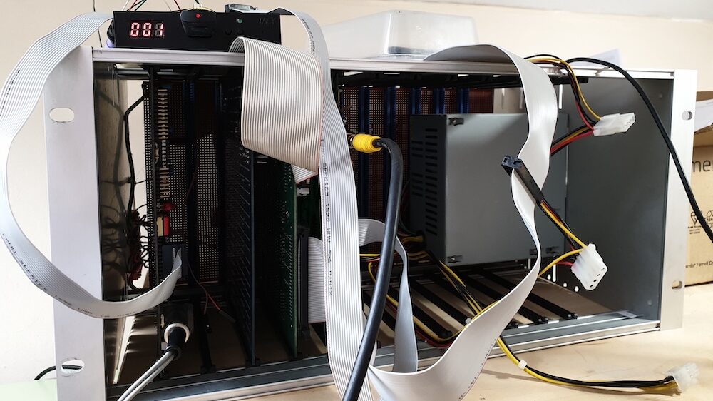
In April 2019 I took delivery of what appears to be a fairly typical Gemini system. The computer consisted of a G811 Z80 CPU card, a MAP80 memory card populated with 64K of Memory, an G812 intelligent video card and a GM829 floppy/hard disk controller card. These were all fitted to a 19 inch rack with a home made Veroboard based backplane. All that was needed was a power supply, a suitable keyboard, disk drives and software. Hmmm!
There were a couple of interesting details regarding the machine, the first is that it includes RP/M version 2.2. This is odd as version 2.2 of RP/M was (supposedly) never released, the version numbers leapt from V2.1 to V2.3 to avoid confusion with version 2.2 of CP/M, this was confirmed in an article written for 80-bus news by RP/Ms creator Richard Beal (80-BUS vol. 3 iss. 6 p. 9).
The second interesting thing is that there is also an EPROM containing the Gemini Boot ROM for 8 inch Disks. This appears to be written by Roger Brooks, and, based on the included source code listings and manuscript amendments, this would appear be the machine he created it on. So, if Roger is reading this or anyone knows anything about Roger please get in touch via twitter @johnnewcombeuk (https://twitter.com/johnnewcombeuk).
See it for yourself on YouTube!
To see the restored machine in action check out https://youtu.be/R6VS9GwD-bw. Dont forget to Subscribe!
Power Supply Unit
For the PSU I opted to use an ATX PSU with a 24 pin connector. I used a 24 pin extension lead to attach to the Gemini backplane which meant that the PSU could simply be plugged into the Gemini and swapped as required. The Gemini documentation suggests that the usual +12v, +5v, -12v and -5v supplies are required. However the later ATX PSU units do not tend to supply -5v. Checking the circuit diagrams for the cards I am using showed that a -5v supply was not actually required making things simple.
A Two Card System
The CPU board includes, ports for an RS232 serial device, a keyboard and a cassette tape recorder. The card also includes an EPROM based system monitor called RP/M (see below). The card is configured using a series of wire straps placed on DIL headers and was, as you would expect, configured to use the external G812 video card I had.
My initial aim was to see the system running with the minimum of hardware, namely the CPU board and the memory board. By making the connection between pins 6 and 7 on link LKB1 on the CPU board I configured the system to use the serial port for input/output. In the end I added a small jumper that could be used as required to switch between using the serial port and the video controller. By using the serial port for control, all that was required was to create a short lead and connect to a machine running a terminal emulator set to 300 baud (7E1).
nspection of the CPU board showed a couple of issues, the first was rusty pins on a couple of ICs. In this case they were the two Proms used for addressing. Unfortunately the affected pins broke off flush with the plastic body of the IC as soon as they were disturbed. However, by grinding away a slither of the plastic IC casing with a Dremel, fresh metal was exposed allowing me to attach some pins from a donor IC. The second issue was that the EPROM that contained the system monitor had been inserted incorrectly and seemed to have been splashed with a large blob of paint. This was easily remedied before powering up the two card system.
   57344 bytes - RP/M for Gemini V2.2

   ** RP/M ready **
   *_
At this point I was able to use the monitor to inspect and set memory, so I dumped the contents of the RP/M EPROM to the screen of my terminal emulator and pasted this into a text file for safe keeping.
For the knowledgable amongst you, you will notice that the Version of RP/M is 2.2. This is odd as version 2.2 of RP/M was (supposedly) never released, the version numbers leapt from V2.1 to V2.3 to avoid confusion with version 2.2 of CP/M, this was confirmed in an article written for 80-bus news by RP/Ms creator Richard Beal (80-BUS vol. 3 iss. 6 p. 9).
A Three Card System
By removing the connection between pins 6 and 7 on link LKB1 on the CPU card and inserting the video card, the system proudly displayed the ready message on the connected composite monitor.
     IVC Monitor V2 - 1982

   57344 bytes - RP/M for Gemini V2.2

   ** RP/M ready **
   *_
However, without a keyboard, not much more could be achieved.
Parallel ASCII Keyboard Converter
The Gemini was designed to use a parallel ASCII keyboard and, whilst I had an old Apple II clone keyboard that probably could have been coaxed into life, I wanted a keyboard with function keys and a full set of cursor keys. I decided that until I could obtain an original Gemini keyboard, the best solution would be to use a PS/2 keyboard and make a simple Arduino based PS/2 to parallel ASCII adapter. I used the small Arduino Micro and created a sketch to do the trick.
The sketch is described here https://bitbucket.org/johnnewcombe/geminikeyboard/src/master/ and the wiring diagram to connect the Arduino to the IVC card and the PS/2 connector is shown in Appendix A – PS/2 to Parallel ASCII Converter Wiring Diagram.
Update 2020: Since building this device it has been suggested that the Arduino Micro cannot handle the the current draw of the Gemini keyboard circuits and on paper, this may well be true. All I can say is that in practice, in the year or so it has been in place, there hasn’t been an issue with this solution.
Once I had the keyboard connected and working, I needed to try and run some software.
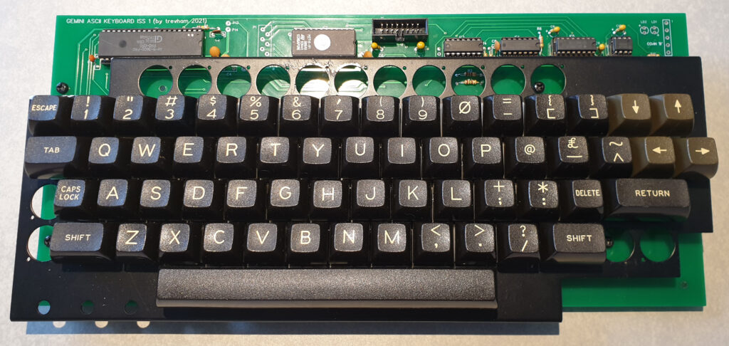
Update 2021: In October 2021 I was fortunate to have been sent a circuit board by Trevor Hambleton allowing me to build my own keyboard. Trevor designed the circuit board to take the Futaba type keyswitches found on many BBC Micro systems. The board uses the AY3600 Pro encoder along with an EPROM to map the keypresses to the codes. I built it within an hour or so and it works reasonably well but probably could do with a little fine tuning in terms of the key codes. I can’t blame Trevor for that though as he used the codes from my Arduino code, so all down to me really.
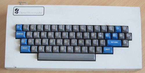
Update 2022: In August 2022 I was fortunate enough to find a genuine Gemini keyboard for the system, I have since passed Trevor’s completed design to Neal Crook.
MBasic (Basic-80)
RP/M is a system monitor written by Richard Beal specifically for the Gemini system and is uses a subset of the CP/M api in that something written ‘against’ RP/M will also run on CP/M the reverse is not necessarily true as RP/M supports only one sequential file being opened at a time and random access is not supported. RP/M was designed support cassette based storage rather than disks, although it will allow booting to disk. Having said that, it is reported that the CP/M version of MBasic and Digital Research’s ZSID Dynamic Debugging Program will run under RP/M, so, given the absence of any form of disk storage this seemed to me to be the logical next step, so I downloaded the binary from one of the many CP/M repositories with the aim of somehow getting it into the machine.
Despite the absence of MBasic on cassette tape, I had a few options to explore. The first was to try and create a .wav file containing MBasic in cassette format (KCS/CUTS). The difficulty here is that whilst is is reasonably easy to create a .wav audio file from an array of bytes, there is more to a Gemini tape archive than just a stream of audio. The Gemini RP/M tape system adds a header to the stream including a filename and, on the basis that an error results in a prompt to rewind the tape before continuing, it is safe to assume that each block of data (128 bytes) includes a frame number and checksum.
he second option is to enter the byte values directly into the monitor, or rather, paste the data into a terminal emulator window. It is an approach that has worked for me before. By ensuring that each CR/NL is followed by a short delay, the system can easily cope with the pasting of a large amount of data. So for this to work is was necessary to switch back to using the RS232 port with a terminal emulator (see section A Two Card System).
The first task was up the speed of the serial port from 300 baud to 9600 baud. This can be done at the RP/M prompt e.g.
   ** RP/M ready **
   * UD 9600
After entering this command, change the speed setting of the terminal emulator to match. Next set the CR delay to 200ms, this value was determined from trial and error. The higher the value, the more reliable and the slower the transfer is, 200ms seems to be optimal. I tend to use Minicom as a terminal emulator which can be configured by selecting the Meta Z (typically Esc+Z) to bring up the main menu, from here the Terminal Settings option can be selected in order to set the delay.
Next, the MBASIC.COM binary file needs to be converted to a HEX file in the following format (see Appendix B – Creating an RP/M Hex File) and pasted into the terminal window.
   S 100
   c3 8c 5d 7a 29 dc 29 06 44 bf 11 9e 45 ec 14 63 18 86 39 40 19 18 15 95 14 67 14 51 16 e6 43 7d 14 d1 14 ee 14 01 44 9c
   16 0e 45 89 20 20 43 85 15 73 44 03 20 2b 1e c0 22 5d 44 c9 0c c9 0c fd 1f 94 16 84 20 00 00 24 20 ee 14 7c 44 7d 44 82
   44 c4 44 e3 3c 10 16 d3 15 7c 22 ...

   ... 38 31 0d 0a 00 00 00 00 00 00 00 00
   .
The S 100 RP/M command allows data to be set in memory starting at address 0100h. In this example each row has 40 hex bytes although anything from 1 to 42 is possible the more hex digits in the row, the quicker the transfer will be. The final full stop should return you to the RPM prompt.
After 2-3 minutes, all 24340 bytes should have been entered and time to see the results. Press I to run the code fro 0100h e.g.
   ** RP/M ready **
   * I
   BASIC-80 Rev. 5.21
   [CP/M Version]
   Copyright 1977-1981 (C) by Microsoft
   Created: 28-Jul-81
   31538 Bytes free
   OK
The files below contain the RPM txt files for MBasic and ZSID.
Creating a Cassette Tape of MBasic
This turned out to be far easier than expected. I knew that if the method described above was used to enter data using the RS232 port, it would not be possible to switch to the cassette interface to save the program to tape. This is due to the serial hardware being used for both RS232 and cassette. However, it turns out that the G811 CPU board can support both the IVC and RS232 as input with IVC providing the display. Therefore with the configuration set to use the IVC (see section A Three Card System) data can still be entered using the RS232 port.
By using the PS/2 keyboard to set the serial baud rate to 9600 e.g
   ** RP/M ready **
   * UD 9600
The process described in the above section (Running Some Software) can then be used to load MBasic into memory although I did find it necessary to set the character delay to 50ms and the CR delay to 250ms. Once the data has been loaded all that is required is to tell RP/M the size of the program using the L command before switching to cassette using UC and writing the program to tape e.g.
   * L BE
   * UC
   * W MBASIC
Once the recording is complete it can be tested by using the R command e.g.
   * R MBASIC

   Insert file: MBASIC
   Start Playing Press return
   ****************************...

   Remove file: MBASIC
   Press return
The program can then be run with the I command e.g.
   * I
   BASIC-80 Rev. 5.21
   [CP/M Version]
   Copyright 1977-1981 (C) by Microsoft
   Created: 28-Jul-81
   31538 Bytes free
   OK
For details of the tape connector see Appendix C – Tape Connector.
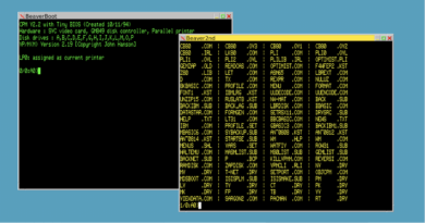
The XBeaver Gemini Emulator
In order to take things further I needed to get up and running with a floppy disk solution to boot CP/M but before that I needed to obtain some disks.
John B Hanson (http://www.cccplusplus.co.uk/xbeaver.html) has created an emulator that can emulate, amongst others, the Gemini system and after contacting him via the UK Vintage Radio Repair and Restoration forum (https://www.vintage-radio.net/forum/showthread.php?t=156106) he very kindly sent me some Gemini CP/M images in .DMP format. As his emulator supports DMP format, I thought it would be useful to get it up and running.
The code can be downloaded from http://www.cccplusplus.co.uk/xbeaver.html and can be compiled for many systems.
XBeaver can be downloaded and compiled with make on linux. However, with my linux of choice being Arch Linux and my laptop being a Macbook Pro I found myself struggling to compile it. Arch was just too new, and my Mac wasn’t Linux.
I tried using a distribution such as CentOS within Virtualbox on my Mac which worked but was slow and regularly stopped working. In the end I came up with a much better solution by running XBeaver in a Docker Container on my Mac. Docker works with Windows and Linux too so I expect it will work just the same with those platforms.
I have detailed the installation etc. in the article Running XBeaver with Docker.
Configuration
The default configuration gave me an all singing all dancing Gemini system, however, as I was looking to emulate my own physical system I decided to start with a minimalist configuration.
The basic xbeaver.cfg file I used was as follows.
   verbose
   cpuclock 4
   board 0xfe gm813_mmu
   board 0xb0 gm832 BeaverBoot planes green
   board 0xb8 serial_8250 bvrnet ~/beaver/network
   board 0xe0 gm829_floppy -debug DSZ -geometry DP35.2.10.512 ~/beaver/images/GM512_ORIGINAL.DMP
   binload 0xf000 ~/beaver/roms/RPM_2.3.ROM
   byte 0f0a8 21 00 f0 #Patch top of ram for RPM
Note that I am using version 2.3 of RP/M (see below).
A Note about RP/M Versions
RP/M is one of the monitor programs, supplied in EPROM, that was available for the G811 processor board. Version 0.1 was the initial release, the second enhanced version was 2.0. When the MAP256 memory board was released there was, under certain hardware combinations, a conflict with RP/M when it was trying to detect if a disk was present. This was entirely due to the MAP256 board, however, a small patch was made available for RP/M to deal with the anomaly, this was deemed to be version 2.1. Version 2.2 was never released in order not to be confused with CP/M 2.2 and the final version was 2.3 which had some enhanced disk boot routines.
My system was supplied with version 2.2 which, according to Richard Beal, the authors of RP/M, never existed. It appears that 2.2 I is a patched version of 2.1 to work with a different disk arrangement. Thanks go to John B Hanson for determining this. As a result I have now been able to create version 2.3 for use with both Xbeaver and the real hardware. The images are available here Gemini_80-Bus_Resource (ROM Images).
Upgrading RP/M to 9600 Baud
When using the serial port for keyboard/screen IO using a terminal emulator I was manually switching from the default 300 baud to 9600 baud. In order for RP/M to default to 9600 baud a small patch to RP/M can be made. The GM811 (Z80 CPU) documentation shows a whole list of divisor values that can be used to set the default serial port speed.
F009 is the location of the two byte divisor. To set the default speed to 9600, set the values as follows.
   F009 = 00
   F00A - 0D
Connecting a Gotek Floppy Disk Emulator
Preparing Disk Images
I was keen to get a floppy drive working with the Gemini and, as I had access to some CP/M boot disks in .DMP format I thought that using a Gotek device (http://www.gotekemulator.com/) with the FlashFloppy firmware written by Keir Fraser (https://github.com/keirf/FlashFloppy) would be a sensible first step. Whilst this took me some considerable time to understand what was required, it turned out to be quite easy to acomplish.
Disk Layouts and Disk Images
GEMDDDS
The GEMDDDS disk type uses the following disk layout, in otherwords when reading or writing to a disk the sectors are accessed in the following order
    Side 0, Track 0, Sect 0 to 9
    Side 1, Track 0, Sect 0 to 9
    Side 0, Track 1, Sect 0 to 9
    Side 1, Track 1, Sect 0 to 9
    Side 0, Track 2, Sect 0 to 9
    Side 1, Track 2, Sect 0 to 9

    etc...
GEMQDDS 80 Track Disk Layout
The GEMQDDS disk type uses the following disk layout.
    Side 0, Track 0, Sect 0 to 9
    Side 0, Track 2, Sect 0 to 9
    Side 0, Track 3, Sect 0 to 9

    etc... to track 79 then

    Side 1, Track 0, Sect 0 to 9
    Side 1, Track 2, Sect 0 to 9
    Side 1, Track 3, Sect 0 to 9
Gotek and .IMG files
Typically IMG files are raw binary files with the sectors in order as they would be accessed by CP/M. This can be hard to get you head around, and the way to think about it is to simply imagine the sectors numbered from 0 to 1599 (QDDS) in the order that they are accessed by CP/M sector 0 followed by sector 1 until reaching sector 1599, lets call this the image sector numbering. CP/M may think they are interleaved or sequential, but from the images point of view there is no concept or interleaved or sequential, simply a collection of sectors one after the other. The differences between sequential and interleaved are handled by the Gotek configuration.
An example may be useful here even if only to remind me what I have worked out!
If CP/M, configured with a QDDS disk drive, wants to access the 21st sector within the disk image (in terms of image sector numbering this would be sector 20), CP/M will ask for the sector on side 0, track 2 sector 0. If the same were to happen with CP/M configured with a DDDS drive CP/M would ask for Side 0, Track1, sector 0. Because sector 20 is in the same place within the disk image no matter what disk type is in use, the Gotek handles the sequential/interleaved differences.
Image Files
All of the image files I have, are available here, https://bitbucket.org/johnnewcombe/gemini/src/master/disk-images/ (see README.md for details)
Connecting the Gotek
Adding a Gotek (or floppy drive) to the GM829 requires either a SA400 Shugart interface drive with a straight cable or an IBM PC drive with a standard 7 wire twisted cable, see Appendix E – Floppy Interface Connections. The firmware chosen for the Gotek (see below) allows this to be configured in software so either cable type should be suitable as long as the necessary configuration option is set in FlashFloppy. This article assumes a straight cable has been used with the Gotek drive select link set to S0. This article also assumes that the GM829 is configured to use Pertec Drives, by ensuring that the setting of Link 1 connects B to C.
There are several Gotek devices to choose from e.g. 24 pin, 34 pin and USB. A 34 pin device should be used, ideally with a 3 digit LED. These are very cheap, the Gotek used in this article was purchased in May 2019 for $15 from a Chinese supplier. It arrived postage free in around 2 weeks.
Configuring the Firmware
The FlashFloppy firmware written by Keir Fraser was installed on the Gotek using the instructions on Keir’s website (https://github.com/keirf/FlashFloppy). This is a simple process, however, version 2.x of the firmware is required as this allows for custom disk formats. Once FlashFloppy is installed, all that is required is to create two text configuration files and place them in the root of the USB stick that is to be used with the Gotek. The files are as follows.
IMG.CFG. This file states that all *.GEMDDDS.IMG files should be treated as Gemini 35 track DDDS CP/M images and that all by *.GEMQDDS.IMG files should be treated as Gemini 80 track QDDS CP/M images.
   # 'GEMDDDS' matches images of the form *.GEMDDDS.img and *.GEMDDDS.ima
   [GEMDDDS]
   file-layout = interleaved
   cyls  = 35
   heads = 2
   secs  = 10
   id = 0
   rate = 250
   bps = 512

   # 'GEMQDDS' matches images of the form *.GEMQDDS.img and *.GEMQDDS.ima
   [GEMQDDS]
   file-layout = sequential
   cyls  = 80
   heads = 2
   secs  = 10
   id = 0
   rate = 250
   bps = 512
FF.CFG. Many of these are default settings, and some relate to optional display and other uogrades, however, the whole file is reproduced here for completeness.
   interface = shugart
   host = unspecified
   pin02 = nc
   pin34 = rdy
   write-protect = no
   side-select-glitch-filter = 0
   track-change = instant
   index-suppression = no
   head-settle-ms = 12
   ejected-on-startup = no
   image-on-startup = last
   display-probe-ms = 3000
   autoselect-file-secs = 2
   autoselect-folder-secs = 2
   nav-mode = default
   nav-loop = yes
   twobutton-action = zero
   rotary = full
   display-type = auto
   oled-font = 6x13
   oled-contrast = 143
   display-off-secs = 60
   display-on-activity = yes
   display-scroll-rate = 200
   display-scroll-pause = 2000
   nav-scroll-rate = 80
   nav-scroll-pause = 300
   step-volume = 10
   da-report-version = ""
   extend-image = yes
Booting the System
Once the Gotek is connected and configured all that is required is a reset of the CPU and CP/M should be up and running.
   57344 bytes -  RP/M for Gemini V2.1
   Executing boot

   Gemini Multiboard Auto Density System (1.4)

       32k CP/M vers 2.2
   A:>
Adding a Real Floppy Disk Drive
As I was completing the work with the Gotek, I was given a very dirty Teac FD55F floppy disk drive. The Gotek is fantastic for getting software to the machine but its not very ‘Retro’. I cleaned up the drive reattached the resistor R13 which had been fed trough a switch. I assume this is a mod that allows the disk to be switched between 40 and 80 tracks. My basic GM815 64K system disk image is a 35 track image so 40 tracks is good.
I assumed that if I could get the drive working that I would be able to use SYSGEN to transfer the CP/M system to the disk, however, sysgen wouldn’t write to the disk for some reason. I then tried various disk copy utilities (COPY.COM, COPYX.COM, ICOPY etc), these utilities wouldn’t update the system track ether. In the end I wrote a utility that accessed the BIOS routines to read in the first 80 128 byte sectors from disk A: before writing them back out to B:. The only issue I had was that I had to make sure that when the floppy drive was formatted it used the same sector skew (0 in my case) for both A: and B:.
Update (Oct 2020): Once the MFB system was up and running see The_Gemini_80-Bus_Saga_-_Part_2, I was able to create floppy system disks without my sector copy fudge.
Swapping the Gotek with the real floppy means that the system will boot from floppy disk (A:) as originally intended and with the Gotek as disk B: I still benefit from the flexibility the device offers.
CP/M Via the Serial Port
During the writing of this article my GM811 IVC display card developed a fault. This made booting to CP/M a little tricky as the Gemini CP/M is designed to send its output to the IVC or SVC display card. John B. Hanson provided a patch to direct CP/M output to the serial port, therefore, by switching back to using the serial port (see section A Two Card System) I could at least use the machine until such time as the IVC is sorted. The patch sacrifices the printer routines, however, for the purpose of testing CP/M, it works well.
The patch was implemented during the .DMP to .IMG conversion and the disk image is provided below. This image was designed to operate the serial port at 300 baud.
Configuring CPMTOOLS
Now that I have a Gotek bootable Gemini system, I thought that it may be an interesting exercise to see if I could use cpmtools (http://www.moria.de/~michael/cpmtools/) to manipulate the images as the product works on MacOS and Linux, the two operating systems I use the most.
To install on MacOS use brew e.g.
$ brew install cpmtools
Before I could start with the cpmtools utilities I needed to create a suitable disk definition.
The disk definitions for cpmtools are located in a text file, the path below shows the Arch Linux and MacOS path, other systems may vary. Some Ubuntu systems may use /etc/cpmtools/diskdefs.
/usr/local/share/diskdefs
There are several disk formats that can be used with the Gemini e.g.
   GEMDDSS: 164K, 35 Track, Single Density, Single Sided
   GEMDDDS: 340K, 35 Track, Single Density, Double Sided
   GEMQDSS: 388K, 80 Track, Double Density, Single Sided
   GEMQDDS: 788K, 80 Track, Double Density, Double Sided
The existing images I have are of the GEMDDDS and GEMQDDS type. In order to support GEMDDDS within cpmtools, the following disk definition should be added to the diskdefs file. Note that GEMDDDS is treated by the Gemini BIOS as 70 tracks (2 sides of 35) with 10 sectors per track, I have yet to determine the GEMQDDS format as 160 tracks at 10 sectors or 80 tracks 20 sectors doesn’t work properly.
   diskdef gemddds
     seclen 512
     # double sided disk format, 35 tracks * 2 sides
     tracks 70
     sectrk 10
     blocksize 2048
     maxdir 128
     skew 1
     boottrk 2
     os 2.2
   end
To create a blank disk image I was expecting to be able to use the mkfs.cpm command (see http://www.moria.de/~michael/cpmtools/), however, this failed to give me a disk that was of the correct size. In the end I used a few snippets of python code to create a file of the correct size and transferred the first 20 sectors directly from the existing bootable 35 track disk image. This simply required some Python to read the 340K disk image into byte array, slicing the array to take the first 20 sectors before writing that to a new binary image. The remaining sectors were filled with the value E5h for no other reason than to comply with tradition for freshly formatted disks.
With this complete, the image can be checked with the cpmtools utility fsck.cmp e.g.
fsck.cpm -f gemddds mydisk.img
Get MBASIC from the 340K disk (note that the -f parameter specifies the respective format)
cpmcp -f gemddds mydisk.img 0:MBASIC.COM mbasic.com
Once complete the image was transferred to the Gotek and the system was booted.
To check the bios disk definitions STAT and DISKINFO can be used (these are both available on the 340K disks posted above). This is the 340K disk image.
   A:> STAT A: DSK:

      A: Drive Characteristics
   2720: 128 Byte Record Capacity
    340: Kilobyte Drive  Capacity
    128: 32  Byte Directory Entries
    128: Checked  Directory Entries
    256: Records/ Extent
     16: Records/ Block
     80: Sectors/ Track
      1: Reserved Tracks
DISKINFO shows the disk parameter block (DPB) from within the BIOS.
   A:> DISKINFO A:
   SPT=80 BSH=4 BLM=15 EXM=1 DSM=169 DRM=127 ALO=192 AL1=0 CKS=32 OFF=1
The final disks are avaiable on the reseource page Gemini_80-Bus_Resource#Software_Library_Contents and include a disk for serial access to CP/M and a .DMP image for use within the XBeaver emulator.
There is still work to do as I would like to add a SASI hard disk and have a SCSI2SD (http://www.codesrc.com/mediawiki/index.php/SCSI2SD) card for the very purpose, however, I have not yet been able to obtain a Gemini Bios that supports a hard disk. Having said that, there’s no rush as 788k disks are relatively large in terms of CP/M and make a very useful system.
IVC Hit by Lightning
During my Gemini journey I was originally thwarted by a faulty GM812 IVC video card which failed a couple of weeks after I purchased the machine in May 2019. This tied in nicely with obtaining a working CP/M disk, except it didn’t, as the CP/M version required the IVC Doh! Thankfully, as described earlier, CP/M could be patched to use the serial port for TTY by changing a couple of bytes so I was off and running. However, in parallel with using a serial terminal to talk to the Gemini CP/M, I set about fixing the IVC card.
I started by testing the CRTC in a BBC Micro, and the Z80 in an Acorn Second processor, the CRTC worked fine, however, the Z80 failed miserably. I popped a replacement CPU (remarkably with a date code only 2 weeks from that of the original) into the IVC thinking that I had effected a repair only to discover that all I had, was different set of symptoms i.e. a different kind of flashing on the screen and still no video.
After going around the houses and few false starts, I isolated the issue to the strobe that is meant to activate a read or write to the CRTC, the problem was that there wasn’t one. Things were getting technical, but by removing the CRTC and the CPU I had isolated enough connections to be able to manually test IC 31 a D-Type Flip Flop which under control of the clock strobes the CRTC, it wasn’t working. As this was a soldered in chip, on went the soldering iron and out came the enamelled wire. If you are not familiar with this method of removing solder from through plated holes, here’s how I used it when undertaking an Apple IIe RAM swap Apple_IIe_RAM_Swap_the_Easy_Way. Naturally a decent socket was fitted with a new SN74S74 D-Type Flip Flop, alas, the card was still not working correctly and I started to think that it had been hit by lightning.
In order to further test the IVC card, a test ROM was created designed to replace the IVC MON ROM. The code was designed to test the addressing and to create signals of the CPU’s IORQ output, it is this output that strobes data into the CRTC. The idea came from multiple sources over on https://www.vintage-radio.net, the final code was provided by Neal Crook.
The memory map of the IVC system is as follows;
   0000 - 1FFF ROM            8000 - 9FFF KEYBOARD
   2000 - 3FFF VDU RAM        A000 - BFFF DATA PORT
   4000 - 5FFF CHAR GEN       C000 - DFFF STATUS (WR)
   6000 - 7FFF STATUS (RD)    E000 - FFFF RAM
And the code supplied by Neal is shown below.
   0000                    ;; in ROM and executes from reset.
   0000                    ;; assume no stack/working RAM so no subroutines
   0000                    ORG 0
   0000
   0000 db 00      loop:   in a, (0)        ; should generate /CS to 6845.
                                            ; Also, use as 'scope trigger
   0002 21 00 20           ld hl, 0x2000    ; video RAM
   0005 7e                 ld a, (hl)       ; read then write
   0006 77                 ld (hl), a
   0007 21 00 40           ld hl, 0x4000    ; char gen ROM or RAM
   000a 7e                 ld a, (hl)       ; read then write
   000b 77                 ld (hl), a
   000c 21 00 60           ld hl, 0x6000    ; status read
   000f 7e                 ld a, (hl)       ; read
   0010 21 00 80           ld hl, 0x8000    ; keyboard
   0013 7e                 ld a, (hl)       ; read
   0014 21 00 a0           ld hl, 0xa000    ; host comms data port
   0017 7e                 ld a, (hl)       ; read then write
   0018 77                 ld (hl), a
   0019 21 00 c0           ld hl, 0xc000    ; status write
   001c af                 xor a
   001d 77                 ld (hl), a       ; write 0
   001e 21 00 e0           ld hl, 0xe000    ; workspace RAM
   0021 7e                 ld a, (hl)       ; read then write
   0022 77                 ld (hl), a
   0023 18 db              jr loop
   0025
Checking pin 20 of the CPU (IORQ) I should have seen a nice signal due to the IN instruction within the loop of the code. However, this was missing as a desperate measure I removed the CPU, bent out pin 20 and reinserted it, the idea was to isolate the IORQ output and negate any possible circuit board issues. Alas, still no signal, it looked like the code wasn’t running, although checking the data bus suggested that the code was doing something. The first thing I did was check the data bus activity. The first block of images shows the activity of D0 to D7 respectively.
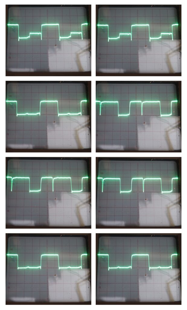
Checking things further shows more activity. The second block of images show the results of wandering around the various component with an oscilloscope and taken from left to right, top to bottom, they depict the following;
- CRTC Pin 24 (R/S)
- CRTC Pin 22 (R/W)
- MUX ICs (10,11,12,15,16,17) Pin 1
- Video Ram IC9 Pin 21 (/WE)
- Video Ram IC9 Pin 20 (/OE)
- CPU RAM IC 13 Pin 18 (/CS)
- CPU RAM IC 13 Pin 20 (/OE)
- CPU RAM IC 13 Pin 21 (/WE)
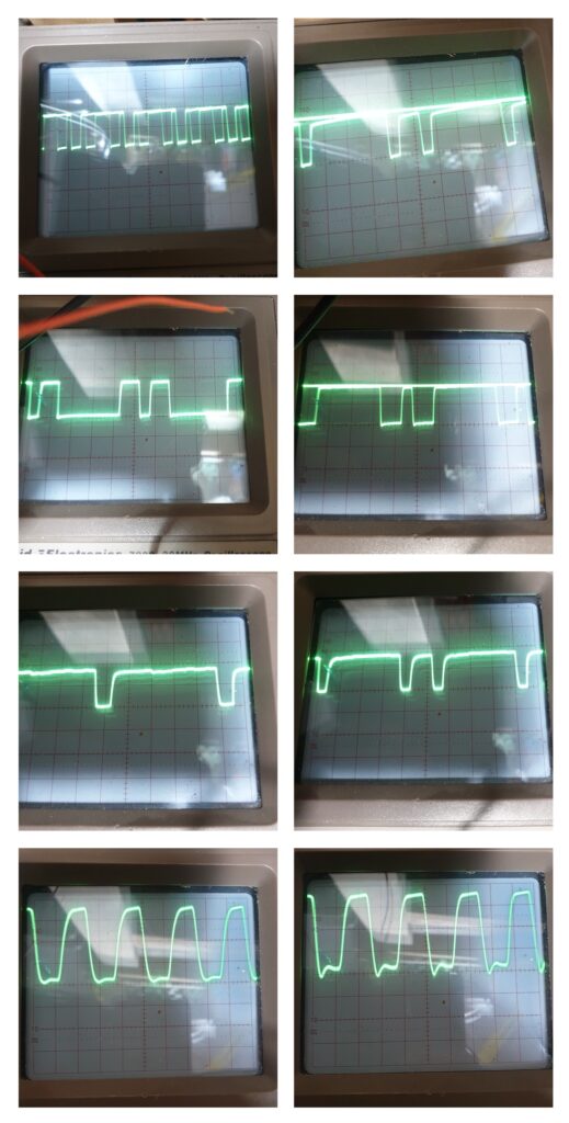
The scope images for Char Gen IC20 Pin 21 (/WE) are identical to Video Ram IC9 Pin 21 (/WE). The scope images for Char Gen IC20 Pin 20 (/OE) are identical to Video Ram IC9 Pin 20 (/0E).
The results suggested all was OK with the addressing and yet there was still an issue with the IORQ output. At this point I started to think that there was an issue with the data bus that was preventing the code when read from memory.
SiriusHardware over on https://www.vintage-radio.net suggested that … when two adjacent data lines look identical with frequent half-logic levels as they do on the uppermost two images, it suggests that the two lines are shorted together either physically (track short/solder splash) or by a fault in one of the devices on the bus.
I checked with a digital multimeter and sure enough D0 was indeed connected to D1. By wandering around the board with a digital meter measuring resistance it was fairly easy to identify the area with the least resistance. The issue seemed to be under the CRTC controller socket, and after lifting the socket slightly and much searching with a very powerful magnifying glass, there it was, a small sliver of copper from one track, touching the other. This was removed with a fine scalpel blade and hey presto I can see pulses on IORQ.
I replaced all the ICs and IVC Monitor and I now have a perfectly good IVC Video card, and to be honest I can’t quite believe it.
My theory of how this all happened is that the original fault of the blown CPU and faulty IC31 is anyones guess, however, when I removed the CRTC to test it I suspect I either damaged the track slightly beneath the socket or disturbed some previous damage. Ho hum…
At this point I must extend my thanks to all those who chipped in Neal, John B, Julie and SiriusHardware over on https://www.vintage-radio.net, without you guys I would have given up long ago.
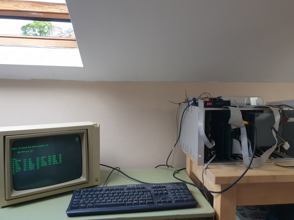
So here it is booted to a 32k CP/M Gotek disk image.
Installing T-Net
T-Net is a networking utility written by John B Hanson that provides a network drive on a Gemini system to be connected to a folder on a system such as Linux. T-Net uses a 9600 baud serial connection between the Gemini and the serving system.
On the Linux server, the Xbeaver emulator (see section The XBeaver Gemini Emulator) is run with a fileserver configuration which typically causes the server to listen on a serial tty such as /dev/ttyS0. Gemini clients can then connect to this server using the T-NET command.
The configuration file (fileserver.cfg) used on my Linux systems is as follows…
   #XBEAVER network server configuration file
   #Define as a server file - eg no main processor activity
   cpuclock 0
   board 0x00 serial_extloop 9600 trace tty tty /dev/ttyUSB0 bvrnet /home/john/xbeaver/network
   echo
   echo bvrnet file server running - use t-net on the clients to connect
In my case I used a USB to Serial connector on the Linux machine connected via a null modem cable to the serial port on the G811 CPU card. All that was required then was to create the folder that I wanted to be served e.g.
$ mkdir /home/john/xbeaver/network
At this point I was able to run XBeaver as a file server
$ ./xbeaver fileserver.cfg
This reported the followng
   Trace tty    : Baudrate requested 9600 set 9600
   Trace tty    : Modem control RTS:1 DTR:1

   bvrnet file server running - use t-net on the clients to connect
Back on the Gemini, I simply had to run TNET N which causes drive N: on the Gemini to be mapped to a folder that is being served by the XBeaver application running on the Linux system e.g.
A:> T-NET N
The folder on theLinux system can now be accessed as a network drive e.g.
A:> DIR N:
Troubleshooting
During my experiments with T-Net I had an issue with the built in serial port of my Linux machine. This was determined by some useful debug information provided by T-Net’s author John B Hanson that would allow me to check the serial link including the cable and UART.
Once the two systems were connected it was possible to check communication by using GEMDEBUG on the Gemini (see Gemini 80-Bus Resource) and a terminal emulator on the Linux machine, e.g. Minicom.
On the Linux machine run the terminal emulator connected to the serial port to be used, using the settings 9600 baud, no parity, 8 bits, 1 stop bit.
On the Gemini it is necessary to start T-NET and then remove it before using GEMDEBUG e.g.
   A> T-NET N
   A> T-NET R
   A> GEMDEBUG
   -
The following GEMDEBUG command sends character 41 on the serial port and this should be seen on the terminal emulator as an upper case ‘A’.
-ob8 41
And the following GEMDEBUG command will display the last character received on the serial port, i.e. the last character to have been sent from the terminal emulator.
-qb8
In my case this identified issues when using the built in serial port. By switching to a USB device my problems were solved
Adding a Winchester Disk
SCSI to SD adapter (SCSI2SD) V5.1.
Now that the machine can boot to CP/M, I would love the machine to operate with a Winchester disk and perhaps a few more peripherals.
Rolling My Own Bios
Without a genuine Gemini Winchester supporting Bios, I decided that I would look into what is required to add SASI disk support to to the existing Bios that I have. The list of requirements was quite short. I needed to add a disk system with controller to the Gemini, learn enough about CP/M, in particular the CP/M 2.2 Bios Functions, to add the hard drive routines to the BIOS and last but not least, learn Z80 assembler, so that I can implement the necessary changes. How hard could it be?
One thing that I decided not to undertake, at least initially was to create a bootstrap process that will boot the system using the disk. My intention was to keep things simple to start with and boot to a floppy that recognised the Winchester.
Selecting a Disk System
The Gemini GM829 Floppy controller includes a Floppy Disk Controller (WD 1797), however, to use a hard disk, a separate hard disk controller is required. The GM829 includes a SASI interface that can be accessed from ports C5/C6 or E5/E6, therefore, all that was needed was to add a disk controller that had a SASI interface. The Xebec controller was used on the original Gemini Winchester disk systems and this connected to an MFM hard disk of the period, however, these seem difficult to get hold of. I decided instead, to opt for the SCSI to SD Adapter (SCSI2SD) V5.1 (http://www.codesrc.com/mediawiki/index.php?title=SCSI2SD) as it is able to emulate the SASI interface of the Xebec controller and provides a modern storage medium. I have no idea if this is the best approach but in for a penny… I chose the Miniscribe IV M4010 Winchester 10Mb disk to emulate as this is a disk of the period.
The emulated disk approach is a good compromise for me as it makes use of the Gemini hardware whilst giving me a modern reliable storage system. In addition, if I add CP/M support for the Xebec controller and a real Xebec based disk system turns up, I am good to go… perhaps.
Many Hours Later…
Once I had the bit between my teeth I was off, I spent many hours learning all about the GM829 SASI interface. I set up a development environment using XBeaver with T-Net to point at a folder on my Mac so that I could edit on the Mac and compile on XBeaver. I then spent many more hours understanding the Gemini CP/M disk organisation, defining disk parameter tables, disk parameter headers and learning the Xebec command interface. I made some very nice Python scripts that that did the work of MOVECPM at a whim, and I learnt Z80 Assembler so that I could implement it all and create several test utilities at the same time.
After some poking and prodding the SASI interface with code, a logic probe and an osciloscope, it started to become clear that getting a SASI disk drive working with a GM829 Floppy/SASI card without a genuine Xebec controller may be very difficult. The problem seems to be that the timing on the SASI select signal is too short for many hard disk systems as it is only active for the duration of the IO write cycle. The later GM849 Floppy/SCSI controller solved this issue by adding a latch to the select line such that it could be set in software as required and then reset. Having said that, it would that a genuine Xebec controller seems to stay selected long enough to be used with a Winchester and may be one of the only controllers that will work with the GM829. Despite much effort, I couldn’t get the SCSI2SD controller to work, even in Xebec quirks mode.
…and then… I received a phone call.
HALT, RESET!
Whilst working to add Winchester support to my system it started to become clear that I would need to modify my GM829 Floppy/SASI implementation in order to latch the select line in a similar way to the GM849 in order for it to work with a modern SCSI disk or SCSI disk emulator e.g. the SCSI2SD. I was contemplating fitting a small board to achieve this when I received a message and then a phone call from Charles O’Brien who was, at the time, based in Blunsdon, Swindon. He has now moved to Hunmanby, East Yorkshire.
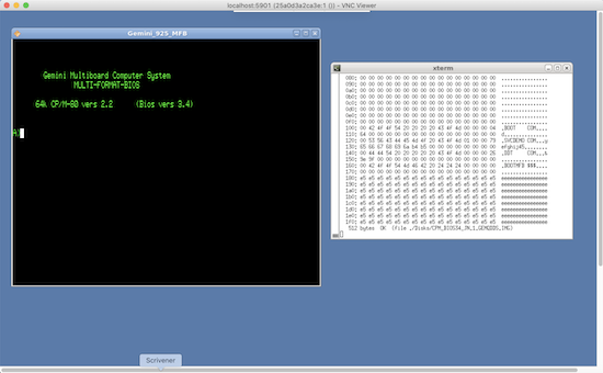
Thanks to the generosity of Charles, I am now the proud owner of a Gemini GM916 Galaxy MFB. The unit includes 5.25″, 8″ and 3.5″ disk drives and a Winchester disk. The machine had been owned from new by Charles and had been used when he ran a consultancy business called Obsys Ltd.
The Multi Format Bios (MFB) allows CP/M to be configured for hundreds of floppy disk formats from many manufacturers and is ideally suited to converting from one format to another. The machine was purchased from a company called Timeclaim Ltd located in Woodbridge, Suffolk who also provided service, support and updates. The documentation that came with the machine was mostly produced by Timeclaim Ltd.
What this means of course is that there is a new chapter be added to the 80-Bus Saga or in this case at least, a new article, namely The Gemini 80-Bus Saga – Part 2.
A Final Upgrade
After I started writing the follow-on article The Gemini 80-Bus Saga – Part 2, User qazxsw123 on (https://www.vintage-radio.net/) posted a disk image of GM555, a CP/M version with bios version 3.5, for which I am very grateful. This is a much improved version of CP/M in that it can be configured very easily using the GENSYS utility rather than using CP/Ms SYSGEN. This is the same process as that used for the MFB version of CP/M and is detailed in the article The Gemini 80-Bus Saga – Part 2.
Having a copy of GM555 has allowed me to upgrade the rack based system so that it now supports both GEMQDDS and GEMDDDS disks, both physical disks and using the Gotek. This makes the system perfect for transferring software and files between these two popular formats.
Appendix A – PS/2 to Parallel ASCII Converter Wiring Diagram
This is the wiring diagram for the PS/2 to parallel ASCII keyboard converter described in the text. The associated sketch is described here https://bitbucket.org/johnnewcombe/geminikeyboard/src/master/.
   IVC Keyboard Connector              Arduino   Usage

            1 ------------------------- VIN
            2 ------------------------- Pin 12    STRB
            3 N/C
            4 N/C
            5 ------------------------- Pin 10    D5
            6 ------------------------- Pin 9     D4
            7 ------------------------- Pin 11    D6
            8 ------------------------- GND
            9 N/C
           10 ------------------------- Pin 7     D2
           11 ------------------------- Pin 8     D3
           12 ------------------------- Pin 5     D0
           13 ------------------------- Pin 6     D1
           14 N/C
           15 N/C
           16 N/C

   PS/2 Keyboard Connector         Arduino Pin   Usage

           5V ------------------------- 5V
          GND ------------------------- GND
          CLK ------------------------- Pin 2     CLK
         DATA ------------------------- Pin 3     DATA
Appendix B – Creating an RP/M Hex File
The following Python script will take the binary file MBASIC.COM and create a HEX file suitable for pasting into a terminal emulator. See section Running Some Software.
   #!/usr/bin/env python3
   LINE_LENGTH = 22 # Number of entries passed to the RP/M monitor per line, should be less than 42.
                    # 22 seems optimal as it reduces the number of carriage returns issued.

   def write_rpm(filename, rawdata):

       rpm_file = open(filename, "w")
       rpm_file.write("S 0100\r\n")

       count = 0;
       for byt in rawdata:
           rpm_file.write("{0:02x} ".format(byt))
           count +=1
           if count % LINE_LENGTH ==0:
               rpm_file.write('\r\n')

       rpm_file.write("\r\n.\r\n")
       rpm_file.write("L {0:02x}\r\n".format(int(count / 128)))
       rpm_file.close()

   if __name__ == '__main__':

       # Read the binary file
       data = open("MBASIC.COM", "br").read()

       # create abyte array
       rawdata = bytearray(data)

       # create rpm package file
       write_rpm("mbasic_rpm.txt", rawdata)
Appendix C – Tape Connector
Tape DIN Connector as viewed from the front of the G811 CPU card.
          Input
           \ |
   Gnd    -
           / |
          Output
Appendix D – Converting from .DMP to .IMG Format
Python script used to convert from .DMP to .IMG image format.
   #!/usr/bin/env python3

   DATA_LENGTH = 512
   HEADER_LENGTH = 8

   def write_raw_interleaved(filename, rawdata):

     # create output file
     raw_file = open(filename, "wb")

     # get sectors from raw data
     sectors = list(get_chunks(rawdata, DATA_LENGTH + HEADER_LENGTH))

     # write the sectors without the .DMP 8 byte header
     for sector in sectors:
       raw_file.write(sector[HEADER_LENGTH:])

     # all done
     raw_file.close()


   if __name__ == '__main__':

     # Read the binary file
     data = open("GM512.DMP", "br").read()

     # create a byte array
     rawdata = bytearray(data)

     # write the .IMG file
     write_raw_interleaved("GM512.IMG", rawdata)
Appendix E – Floppy Interface Connections
Shugart Pin Assignments
   Pin Name    Dir  Description
   --- ----    ---  -----------
   2   /DCD    -->  Disk Change Detect
   4   /INUSE       A common open-collector LED driver signal? I have never seen this signal used anywhere.
   6   /DS3         Device Select 3.
   8   /INDEX  <--  Index
   10  /DS0    -->  Device Select 0
   12  /DS1    -->  Drive Sel B
   14  /DS2    -->  Device Select 2
   16  /MTRON  -->  Motor On
   18  /DIR    -->  Direction
   20  /STEP   -->  Step
   22  /WDATE  -->  Write Data
   24  /WGATE  -->  Floppy Write Enable
   26  /TRK00  <--  Track 0
   28  /WPT    <--  Write Protect
   30  /RDATA  <--  Read Data
   32  /SIDE1  -->  Head Select
   34  /RDY    -->  Drive Ready/Disk Changed
IBM PC Pin Assignments
   Pin Name    Dir  Description
   2   /REDWC  -->  Density Select
   4   n/c          Reserved
   6   n/c          Reserved
   8   /INDEX  <--  Index
   10  /MOTEA  -->  Motor Enable A
   12  /DRVSB  -->  Drive Sel B
   14  /DRVSA  -->  Drive Sel A
   16  /MOTEB  -->  Motor Enable B
   18  /DIR    -->  Direction
   20  /STEP   -->  Step
   22  /WDATE  -->  Write Data
   24  /WGATE  -->  Floppy Write Enable
   26  /TRK00  <--  Track 0
   28  /WPT    <--  Write Protect
   30  /RDATA  <--  Read Data
   32  /SIDE1  -->  Head Select
   34  /DSKCHG <--  Disk Change/Ready
Gemini GM829 Pin Assignments
   Pin Name    Dir Description
   --- ----    --- -----------
   6   /RDY         *Drive Select D/Ready line
   8   /SECP   <--  Index
   10  /DS1    -->  )
   12  /DS2    -->  )Drive Select Lines A-C
   14  /DS3    -->  )
   16  /MTRN   -->  Drive Motor Enable
   18  /DIRN   -->  Direction
   20  /STEP   -->  Step
   22  /WDA    -->  Write Data
   24  /WRT    -->  Write Gate
   26  /TRK0   <--  Track 0
   28  /WPT    <--  Write Protect
   30  /RDA    <--  Read Data
   32  /HSLT   -->  Side Select
   34  /DS4    -->  *Unused/Disk Select D
- The function of lines 6 and 34 are selected by Link 1. e.g. With B linked to C pin 6 is the fourth drive select line. With A linked to B and C linked to D, pin 34 will be the fourth drive select line and pin 6 will be the drive ready line.
Standard 7 Wire Twist
     10   --------.     .--------   10
                   \   /
     12   ----. .---\-/----------   12
               X     X
     14   ----' `---/-\----------   14
                   /   \
     16   --------'     `--------   16

     Pins 11, 13 and 15 are also twisted, however, all odd-numbered pins are connected to ground and are not shown here.
Appendix F – IVC Terminal Codes
General
   07                Bell
   08                Backspace
   0A                Linefeed
   0D                Carriage Return
Cursor Operations
   1C                Cursor left.
   1D                Cursor right.
   1E                Cursor up.
   1F                Cursor down.

   1B 3D <Row> <Col> Cursor addressing.
   1B 3F             Return coordinates and character.
   1B 44             Delete cursor.
   1B 45             Enable cursor.
   1B 59 ..          Define cursor type.
Screen Editing
   0B                Delete line and scroll up.
   0E                Insert line.
   16                Delete character in line.
   17                Insert character in line.
   1A                Clear screen.

   1B 16             Delete character in screen.
   1B 17             Insert character in screen.
   1B 25             Delete to end of screen.
   1B 2A             Delete to end of line.
   1B 5A             Return contents of current line.
Screen Format
   1B 31             Select 80 wide format.
   1B 32             Select 40 wide format.
   1B 33             Select user defined format.
   1B 46 ..          Define user format.
   1B 42             Blank screen.
   1B 56             Video on (un-blank screen).
   1B 49             Video invert screen.
   1B 4A             Video normal screen.
   1B 41             Alternate character generator is default.
   1B 4E             Normal character generator is default.
   1B 4D             Memory lock on.
   1B 4F             Memory lock off
Character Set and Block Graphics
   1B 43 ..          Define character.
   1B 63 ..          Define character set.
   1B 47             Construct block graphics character set.
   1B 48             Duplicate lower character set in upper but invert.
   1B 68             Duplicate lower character set in upper.
   1B 52 ..          Reset point X,Y.
   1B 53 ..          Set point X,Y.
   1B 54 ..          Test point X,Y.
Keyboard
   1B 66 ..          Define function keys.
   1B 6B             Test keyboard status.
   1B 4B             Get keyboard character.
   1B 58             Get one line of input.
Miscellaneous
   1B 57 ..          High speed write to display.
   1B 4C ..          Load user program.
   1B 55             Execute user program.
   1B 50             Return light pen co-ordinates.
   1B 76             Return Version Number
Appendix G – Patching Wordstar 3.0 for the Gemini IVC Card
The following patches can be made to WS.COM in order to support the Gemini IVC Card. All values are Hex.
   049B: C3 67
   052D: 7F
   0649: 1C 00
   064B: 65 63
   064D: 1D 00
   064F: 5B 63
   0651: 1F 00
   0653: 24 64
   0655: 1E 00
   0657: 3E 64

   0248: 19 50
   024A: 02 1B 3D
   0253 to 025D: ALL ZERO
   025E: 20 20 00 00 00 00 00 00 C9
   026D: 02 1B 2A
   0274: 01 0B
   027B: 01 0E
   0284: 02 1B 41
   028B: 02 1B 4E
   0292 to 02A3: ALL ZERO
   02A4: 00 00 C9 00 00 C9 00 00 00 00
   02AE: 01 01
   02B0: 00 00 00
   02D2: 10

   0190: 47 65 6D 69 6E 69 20 49 56 43
   019A to 01AE: ALL 20
Appendix H – Configuring Turbo Pascal 3.0 for the Gemini IVC Card
The following screen definition provides support for the Gemini IVC card. Enter a minus sign (“-“) to set the value to Nothing.
   Send Init                                   : N
   Reset                                       : N
   Cursor Lead In                              : $1B $3D
   Cursor position Command between line/column : Nothing
   Cursor position Command after line/column   : Nothing
   Column First                                : N
   Offset to add to line                       : $20
   Offset to add to column                     : $20
   Binary Address                              : Y
   Clear Screen                                : $1A
   Clear screen also home                      : Y
   Delete Line                                 : $0B
   Insert Line                                 : $0E
   Delete to end of line                       : $1B $2A
   Low Video                                   : Nothing
   Number of rows                              : $19
   Number of columns                           : $50
   Delay after cursor address                  : 25
   Delay after Clear, Delete, Insert           : 25
   Delay after erase to end of line            : 25
