Telstar – Troubleshooting
Here are a few settings, diagrams and documents that may help you get connected.
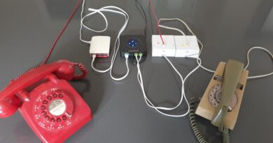
PSTN Access
‘No Carrier’ Issues
One of the most common issues that are experienced when accessing Telstar using a modem occurs after the Telstar modem answers but fails to make a connection. The issue is often due to the caller not sending the ‘back channel’ carrier. This can be determined by listening to the modem signals with some form of monitor. Often these audio tones can be heard over the modems loud speaker, where fitted.
During the modem negotiation period many audio signals may be heard, these should settle down to a high pitched tone and a very low pitched tone. The high pitched tone is sent by Telstar, the low pitched tone, the ‘back channel’ signal should be provided by the callers modem. A missing back channel signal could be due to a faulty modem, a missing DTR or RTS signal from the Terminal/Computer or bad signal level (see below).
VOIP/SIP Lines
Telstar can be accessed using VOIP/SIP lines, in fact Telstar is hosted using SIP lines supplied by sipgate.co.uk, however, the vocoder/codec type must be set to G711u (often specified as PCMU). No other codec types are supported.
Signal Levels
Note that both Line 1 (01756 664433) and Line 2 (01756 664434) use different levels of gain. Line 1 is set to -6db TX and -12db RX and Line 2 is set to -2db Tx and -8db RX. During testing it became clear that these values supported the greatest range of V23 modems, videotex terminals and line types (POTS/VOIP etc.).
Some modems may exhibit overloading. Overloading of the modem can be checked for by connecting a phone to the same socket as the modem (rather than plugging the phone into the back of the modem) and leaving the handset off hook during the data call. If the additional line attenuation that the phone introduces, helps, then overloading may be the problem.
US Robotics Modem (Courier V. Everything, Dual, HST Dual etc.)
When accessing via PSTN (Public Switched Telephone Network) the modem must be set to V23 1200/75 baud. That is receiving at 1200baud and transmitting at 75baud.
The most common issue witnessed by users connecting is with US Robotics modems where the S register S34 has not been set. The full configuration for US Robotics modems is:
AT&F
AT&B1
AT&H1
ATS0=1
ATS34=8
ATS19=2
ATE0
AT&W
OEL Telemod 2/Prisim 1000 Modem
This modem is an example of a modem with no CTS/RTS however, it does provide a signal that can be used to indicate CTS.
                                         Pin numbers when viewing the socket
                                             from the rear of the modem.

Pin 1 RXD
Pin 2 DCD                                                3   1
Pin 3 CTS                                               5     4
Pin 4 TXD                                                  2
Pin 5 GND

Notes:

* RTS is not needed as CTS is permanently enabled.
The following describes how to connect the modem to a BBC or Torch computer see the BBC Microcomputer section below for BBC Microcomputer connection details.
BBC          OEL Telemod 2/Prism 1000

With embossed line on BBC 5 pin 270 deg plug pointing away from the PSU.

GND     ---------------- Pin 5
CTS     ---------------- Pin 3
TXD     ---------------- Pin 4
RXD     ---------------- Pin 1
RTS          not used
OEL/Prism Networking Interface (Acoustic Modem)
                                         Pin numbers when viewing the socket
                                             from the rear of the modem.

Pin 1 RXD
Pin 2 Not Used                                            2
Pin 3 CTS                                              4     5
Pin 4 TXD                                               1   3
Pin 5 GND

Notes:

* RTS is not needed as CTS is permanently enabled. On some devices the lableing on the rear of the modem does not reflect the connections here. I can only assume that the pin numbering scheme of the 240 deg DIN connector used by OEL/Prism is different to the 'standard' numbering shown above. In addition the rear labelling of the device refers to CD rather than CTS. On the devices I have seen CTS/CD is permanently set with or without a carrier therefore I have referred to is as CTS here, this is inline with the companies other devices.
Dowty Quattro (DM424X) Modem
AT&F
    AT&D2
    AT&C1
    AT&I3
    AT&R1 (should be default but seems not to be)
    ATS0=1
    ATS37=60
    AT&W

B   Bell/CCITT     0          &M  Sync Mode      0
E   Echo           0          &P  MB Ratio       1
F   Format         3          &R  RTS/CTS        1
L   Loudness       2          &S  Switch Ctrl    0
M   Speaker        1          &T  RDL Inhibit    4
Q   Quiet          0          &U  User Flow      0
V   Verbose        1          &V  Dumb           0
X   Results        4          &X  Tx Clk Source  0
Y   Long Space     0          &Y  Ctrl Port      0
&A  Auto-rate      0          *A  Auto-sync      0
&B  Busy           0          *D  DTR Dial       0
&C  DCD Option     1          *F  VF Flow Ctrl   0
&D  DTR Option     2          *G  Calling Tone   0
&E  Error Corr     0          *K  Multi Mode     0
&G  Guard Tone     2          *R  Remote Ctrl    1
&I  Const Speed    3          *U  Multi User     0
&K  Flow Ctrl      3          *X  Sync Clocks    0
&L  Leased Line    0          *Y  Break          0

OK


Reg  Dec  Hex        Reg  Dec  Hex        Reg  Dec  Hex
-------------        -------------        -------------
  0    1   01         17    0   00         34   50   32
  1    0   00         18    0   00         35    0   00
  2   43   2B         19    0   00         36    5   05
  3   13   0D         20    0   00         37   60   3C
  4   10   0A         21   52   34         38  242   F2
  5    8   08         22  246   F6         39   17   11
  6    4   04         23  133   85         40   19   13
  7   40   28         24    0   00         41  249   F9
  8    4   04         25   15   0F         42  251   FB
  9    6   06         26    0   00         43    0   00
 10   14   0E         27    0   00         44    0   00
 11    0   00         28    0   00         45    6   06
 12   50   32         29    0   00         46    0   00
 13    0   00         30    0   00         47   13   0D
 14  168   A8         31  131   83         48   13   0D
 15    0   00         32  104   68         49   17   11
 16    0   00         33    0   00         50   19   13

OK
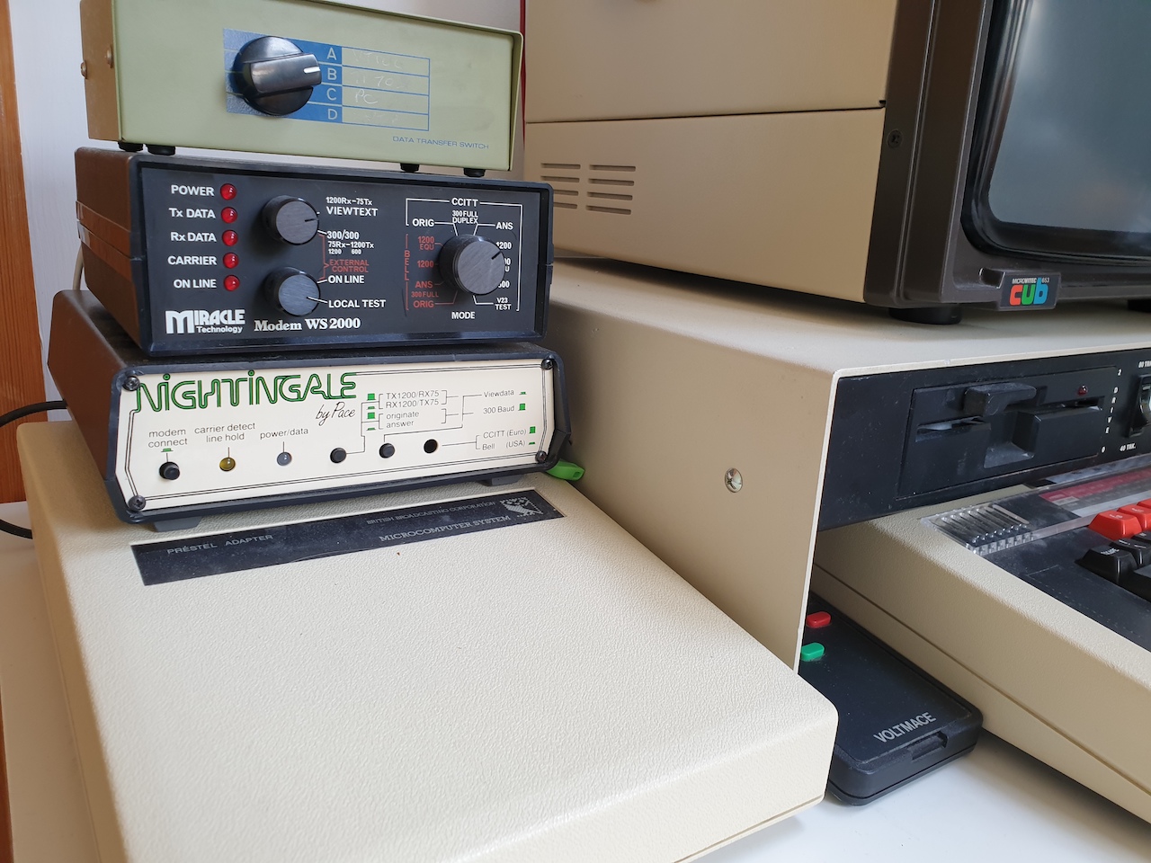
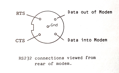
Pace Nightingale Modem Connections
The connections fpr the Pace Noghtingale modem are shown below. Note that line that is embossed on the plug, lines up with the small cutaway shown on the left of the socket.
Trying to Work Out Modem Connections
Many early modems did not have standard DB25/DB9 connectors and were often badly documented, the following is an approach that may help try and determine the connections on these devices. Good Luck!
First determine the signal ground pin. This is often tied to the mains earth, and in such cases can be determined with a continuity check. Failing that opening up the modem may show one of the connections being connected to the ground area of a circuit board etc.
With the ground pin determined and the computer or modem powered on check between the ground pin and the other pins for a steady signal (voltage above or below 3v). If the item you are checking is a computer (DTE) then then a signal is most likely a DTR or RTS. If you are checking a modem (DCE) then the signal could be a CTS or DSR. However, in many cases a modem won’t exhibit a DSR until it receives a DTR, similarly a CTS won’t be present until an RTS is received. Therefore, once the signal ground has been determined and a DTR or RTS signal has been found on the computer connect this signal to each of the modem connections in turn monitoring the remaining modem connections for steady signals. What you are looking for is the modem presenting a signal CTS or DSR in response to receiving a DTR or RTS.
Its not straightforward but with some trial and error and a little understanding of serial connections it can often work out well.
Grandstream 802 Settings
These are the settings that have been found to be the best when calling Telstar from a SIP line with a Grandstream ATA 802 device (or similar).
BBC Micro Connections
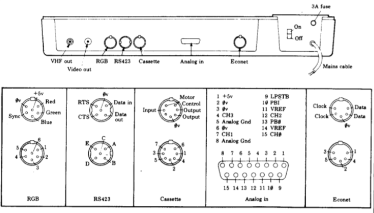
Note that the Acorn produced diagram above does not indicate the pin numbers for the RS423 port. The appropriate plug can be placed in one of two ways, see below
To Connect to a Modem simply connect Data Out to the TXD connector of the modem, similarly connect Data In to the RXD of the modem. RTS and CTS should be connected to the similarly named modem connections, where they exist. If they don’t exist then connect the BBCs RTS back to its CTS.